Description
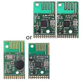
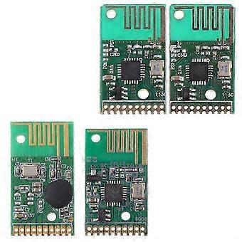
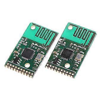
Wireless Module Receiver 6-Channel Remote Control Transceiver Board DIY Kit High quality
brand new and high quality
Features:
Made of high quality material, solid, durable and good performance, stability and reliability.
The 2.4G ISM band can be used without interference at the same for time.
High-performance baseband processing chip, fast remote control and high security level.
The internal 2.4G program and remote control code program are included, no need to reprogram, use directly.
With 6 input and output functions, it can be expanded, and the output state can be selected to be latched or not latched.
Highly integrated, small size, low power design, no peripheral parts, easy to use.
Widely used in wireless remote, for smart appliances, wireless sensor, samrt home control system and so on.
Decoder board only, other accessories demo in the picture is not included!
Specification:
Material: PCB Board, Electronic Components
Optional Type and Size: app.1.3 x 2.5cm/0.51 x 0.98in
Color: Green
Quantity: 1 Set
Product
Parameters:
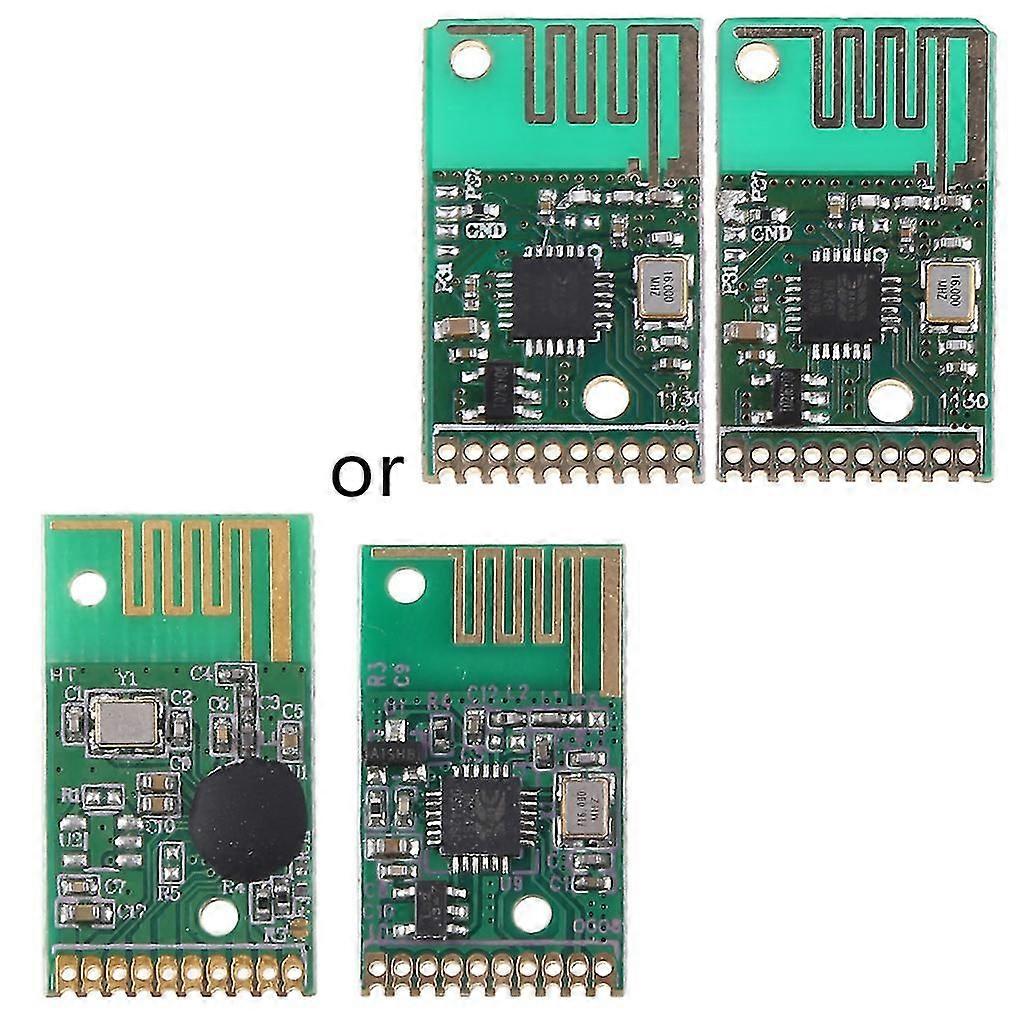
TY24D-TX (Transmitting module)
Working Frequency: 2.4G
Working Voltage: 2.5-3.6V
Emission Current: 0-15mA
Output Power: 5db
Sleep Current: 3.5uA
Modulation Method: GFSK
Maximum Speed: 1M
Control Port: 6-way button input
Coding Form: learning code
Antenna Form: PCB antenna
Reference Distance: 50 meters (accessible)
TY24D-RX (Receiving module)
Working Frequency: 2.4G
Working Voltage: 2.5-3.6V
Emission Current: 23mA
Receive Sensitivity: -85dBm
Modulation Method: GFSK
Data Channel: 6 channels
Output Status: Latched/Non-Latched
Output Level: 0-high level
Coding Form: Learning code, automatic identification Remote control address data
Antenna Form: PCB antenna
Reference Distance: 50 meters (accessible)
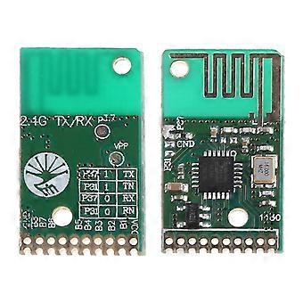
Pin Introduction:
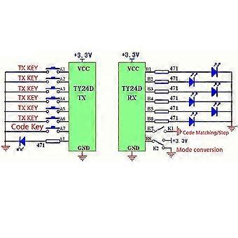
TY24D-TX:
VCC: +3.3V(2.5-3.6)
B1-B6: 6-channel data pin, connected to the transmit button, active low
B7: For the code foot, learn the button, active low
B8: Pair of code and emission status indication, LED
GND: GND
TY24D-RX:
VCC: +3.3V(2.5-3.6)
B1-B6: 6-channel data pin, the output is high level, usually 0 level
B7: Pair code/forbidden pair code, ground pair code, dangling forbidden code
B8: Output mode selection, ground is latched output, and VCC is non-latched output
GND: GND
RX Mode Conversion Function:
for Latch Mode: RX output port is normally 0 level state, press the button once, receive the output high level and for latch, press the button again, the receiving output becomes 0 level, the B8 port needs to be connected to GND.
Non-latching Mode: Press and hold the transmit button, receive the output high level, release the button, and receive 0 level. The B8 port needs to be connected to VDD.
Pair Code and Disable Code Function:
TX and RX must be used for the code. RX can only identify the TX with successful code. After the code is successful, the B7 code port must be disconnected (floating) to prohibit other TX pairs, preventing other remote controllers from illegally controlling the code. Your receiving device. The receiving pair code port does not limit the number of pairs of the remote controller (multiple send 1 version) in the allowable code status, allowing several remote control code to be determined by the owner. If the receiving module (RX) is replaced after the code is coded, the original remote control (TX) needs to be re-coded. The remote control can only control its own receiving device. If a remote controller and its receiving device are paired with the code, then learn the other. Receiving the device and learning successfully, the receiving device will no longer receive the information of the remote controller and automatically clear the remote controller. If you need to use this remote control, you need to re-receive the device pair code. The password is a unique 32-bit address that is sent to the other party when the code is paired. Each transmission or reception can only store a unique password. If the code is re-coded, the original password will be cleared.
Testing and use:
After the code is successful, press the B1-B6 transmit button to receive the B1-B6 port output high level. Use the LED to display whether the output function is normal. The open reference distance is about 50m. The for launch is usually in low power mode. Press the for launch button. The emission current. The receiving module can provide 2mA output current to drive 3V LED. If you need to add power drive circuit to drive other large loads, the module power supply can'for t be reversed, and the voltage can'for t exceed 3.6V. Otherwise, the device needs to provide stable voltage. A 47Omega resistor and a 10UF capacitor are placed in front of VDD to power the module. The module is a built-in antenna of the PCB. The antenna must leave the steel plate of the main board. Otherwise, the transmission and receiving distance will be affected. The module can be solde
-
Fruugo ID:
349418530-762172191
-
EAN:
9777478053784